







with maximum scalability!
Discover the 5 key performance advantages of the zero8 product family.


Benefit from maximum efficiency, reliable contact integrity, signal protection, high speed, and durability starting today.
The Zero8 product family from ept has been specifically developed for demanding industrial applications and offers maximum scalability: You can customize the form factors, stacking height, and number of pins to meet your specific requirements. Sockets and plugs are available in low-profile, mid-profile, and high-profile form factors, in both straight and angled versions. The plug is also available in an x-high-profile version, meaning that the zero8 connector can accommodate PCB spacings between 6 and 21 mm thanks to its various profile heights. You can request a variable number of pins ranging from 12 to 80.
But that’s not all. You also have a choice when it comes to shielding. Do you want both sides of the connector pair shielded or unshielded? Or perhaps just one side shielded? The choice is yours—all Zero8 connectors are fully plug-compatible with one another and can be freely combined, regardless of whether they are shielded or unshielded.
But that’s not all. You also have a choice when it comes to shielding. Do you want both sides of the connector pair shielded or unshielded? Or perhaps just one side shielded? The choice is yours—all Zero8 connectors are fully plug-compatible with one another and can be freely combined, regardless of whether they are shielded or unshielded.

The rugged, double-sided ScaleX connection technology withstands the harsh conditions of industrial applications and ensures reliable contact even under mechanical stress such as shock and vibration. It also compensates for device-side tolerances in all directions when the connectors are mated. EMC shielding effectively protects signals in industrial environments from external influences, and the material composition guarantees a data transfer rate of up to 16 Gbit/s. Furthermore, ept has taken things a step further: the connector geometry was designed so that the contacts cannot be damaged even in the event of incorrect handling.

Superpower: EFFICIENCY
Space-saving design with a 0.8 mm pitch
All Zero8 connectors feature a contact pitch of 0.8 mm in a space-saving configuration to minimize the space they occupy on the printed circuit board. Despite the small pitch, the contacts engage with each other on their smooth surfaces rather than on the rough stamped edges. This ensures significantly greater resistance to abrasion, for example during micro-movements.
Variable number of contacts from 12 to 80
Zero8 is available with 12, 20, 32, 52, or 80 contacts for maximum flexibility in your application. The connector is dual-row; for example, a 12-pin connector has 6 contacts in each row. If required, variants with a specific number of pins can also be manufactured, for example, to accommodate larger clearance and creepage distances.
Available in shielded and unshielded versions
You also have a choice when it comes to shielding! Do you want both sides of the connector pair to be shielded or unshielded? Or perhaps just one side? All Zero8 connectors are fully plug-compatible and can be combined as required, regardless of their shielding configuration. In shielded versions, the solder terminals of the contacts are positioned beneath the connector, whereas in unshielded versions they are located on the sides to permit AOI inspection during manufacturing.
Stack heights from 6 to 21 mm
With the straight low, mid, and high profiles, PCB spacing can be achieved at any distance between 6 and 21 mm. Inserting the connector all the way to the stop achieves the minimum possible PCB spacing. The plug and socket can be inserted variably within a range of 1.5 mm to achieve the maximum possible PCB spacing. The remaining 0.8 mm ensures secure contact (anti-over-insertion protection).
Angled designs for applications ranging from 90° to 180°
The angled design, combined with the straight design, allows printed circuit boards to be arranged at a 90° angle to one another, e.g., for backplanes with daughter cards. The combination of two angled designs allows for the arrangement of two PCBs side by side at a 180-degree angle. All of these are available in either shielded or unshielded versions and with 12, 20, 32, 52, or 80 contacts for maximum flexibility in your application.
Develop your solutions with maximum efficiency. With its features, Zero8 ensures that you reach your goals faster while benefiting from an enormous variety of options. Even angled designs for 90° and 180° applications are available.
Free white paper on high speed and EMC »
Request a free sample box »
Find more information here.
Free white paper on high speed and EMC »
Request a free sample box »
Find more information here.


Superpower: CONTACT SAFETY
Innovative ScaleX contact system
ScaleX – this brand stands for robust contact technology in a flexibly scalable connector system. It was specifically designed to combine high mechanical robustness with outstanding high-frequency performance. This combination is unique in the world of PCB connectors.
Two contact pads per pin
Each contact pair consists of two blade contacts and two spring contacts. This redundancy ensures maximum contact reliability—especially in demanding environments subject to shock and vibration—while also delivering exceptional durability and reliability in your application. Furthermore, all contacts are located on the smooth side of the contact surfaces, rather than on the rough stamped edge, as is the case with many other miniaturized connectors.
Shock- and vibration-resistant
Redundancy in all contacts, combined with contact only on smooth, rolled surfaces, results in exceptionally high resistance to shock and vibration. Zero8 connectors have undergone thorough testing and qualification in accordance with the IEC 60512 standard. We would be happy to provide you with our detailed test reports.
High resistance to slippage
Each mated contact pair of socket and plug has an over-insertion range of at least 0.8 mm; that is, this corresponds to the distance from the contact point to the contact tip—the point at which contact would no longer be maintained. This over-insertion range of at least 0.8 mm ensures a correspondingly high tolerance compensation and thus maximum reliability in every application. When the plug is fully inserted into the socket, the over-insertion range increases to up to 2.3 mm per contact pair.
Rated for at least 500 insertion cycles
The Zero8’s contacts are designed to ensure reliable contact even after 500 mating cycles, even when subjected to temperature cycling and corrosive gases. Even if the contacts are not mated 500 times, mating cycles serve as a suitable criterion for assessing the extent to which connectors remain functional under repeated temperature cycling or vibration (“fretting corrosion”).
You will appreciate the Zero8 connector family, which stands out thanks to its innovative ScaleX technology. Rugged and double-sided, it withstands the harsh conditions of industrial applications and ensures reliable contact—even under extreme environmental conditions and mechanical stress such as shock and vibration.
Free white paper on ruggedness »
Request a free sample box »
Find more information here.
Free white paper on ruggedness »
Request a free sample box »
Find more information here.


Superpower: SIGNAL PROTECTION
Newly developed EMC shielding concept
During the development of the zero8, special attention was paid to dual-sided shielding. This ensures interference-free data transmission, as required by many applications, such as those for Industry 4.0 or the IoT. The shielding material used is specifically designed to meet stringent electromagnetic compatibility requirements.
Optimal dissipation of interference currents
The shielding plates are designed to cover a large area with few gaps, ensuring maximum protection. In addition, the large number of contact points between the shielding plate and the printed circuit board allows for optimal dissipation of interference currents. For example, in a 20-pin connector, a shielding plate with a length of 8 mm features a total of 5 solder connection points to the printed circuit board.
Coupling inductance of up to 10 picohenries
In detailed tests conducted by a specialized laboratory, the effects of electric and magnetic field strengths were first simulated and then verified through experimental testing. The results obtained are excellent and can be provided upon request. One of the key measurement results was a maximum coupling inductance of 10 pH achieved with Zero8 connectors.
Alternatively, without shielding
You also have a choice when it comes to shielding. Do you want both sides of the connector pair to be shielded or unshielded? Or perhaps just one side? All Zero8 connectors are fully interconnectable and freely combinable, regardless of their shielding configuration. In shielded versions, the solder terminals of the contacts are located beneath the connector, while in unshielded versions they are positioned on the sides to enable AOI inspection during manufacturing.
The newly developed, double-sided shielding design of zero8 connectors guarantees interference-free high-speed data transmission in industrial environments. The shielding material is specifically designed for components with high electromagnetic compatibility requirements and guarantees a coupling inductance of no more than 10 picohenries for the connector.
Free White Paper: High Speed and EMC »
Request a Free Sample Box »
Find more information here.
Free White Paper: High Speed and EMC »
Request a Free Sample Box »
Find more information here.


Superpower: SPEED
Compatible with PCIe 4.0 and Industrial Ethernet
Zero8 connectors meet the requirements of the PCI Express Gen. 4 and Industrial Ethernet specifications, as required in many applications, such as those for Industry 4.0 or the IoT. In addition to insertion loss, Zero8 demonstrates excellent performance in terms of return loss and crosstalk.
RF signal transmission at 16 Gbit/s +
Zero8 connectors are ideally suited for applications with data transfer rates of up to 16 Gbit/s. Due to its excellent insertion loss characteristics, Zero8 can even be used for applications up to 25 Gbit/s. This outstanding suitability is combined with an extremely robust and durable contact system designed for demanding environments involving shock, vibration, or corrosive gases. This combination is unique.
Additional signal protection through shielding
The dual-sided shielding design ensures interference-free high-speed data transmission in industrial environments. It reliably diverts interference currents through multiple contact points on both circuit boards. The shielding design protects the connector from electromagnetic interference (as a sink for interference), but also shields adjacent components when the connector acts as a source of interference.
SI models available
Zero8 was first thoroughly simulated with regard to its RF characteristics and then tested in laboratory trials. Detailed test reports and SI models for simulations in your application are available.
HighSpeed is the key feature of ept’s Zero8 product family. Simulations using the Zero8 connector system at 16 Gbit/s demonstrate excellent signal integrity, making it ideal for PCIe 4.0 and Industrial Ethernet. We provide the S-parameters for your application simulations.
Free White Paper: High-Speed and EMC »
Request a Free Sample Box »
Find more information here.
Free White Paper: High-Speed and EMC »
Request a Free Sample Box »
Find more information here.


Superpower: ROBUSTNESS
Protection for all contacts
Zero8 is designed so that the contacts remain undamaged even if operated incorrectly. The contacts are concealed within the insulating housing, providing optimal protection against potential mechanical damage, such as accidental contact. This ensures the highest possible level of safety for your application.
Anti-twist protection when plugging in
The polarization built into the insulator prevents incorrect mating due to twisting of the connectors. This means that the plug and socket can only be mated if they are aligned in a specific direction. In addition, distinct guide elements in the insulator ensure secure mating.
Mechanical relief provided by two board locks
Two board locks per connector are soldered onto the circuit board to provide mechanical strain relief for the signal contacts. This prevents the signal contacts from breaking away from the solder joint when the plug and socket are disconnected.
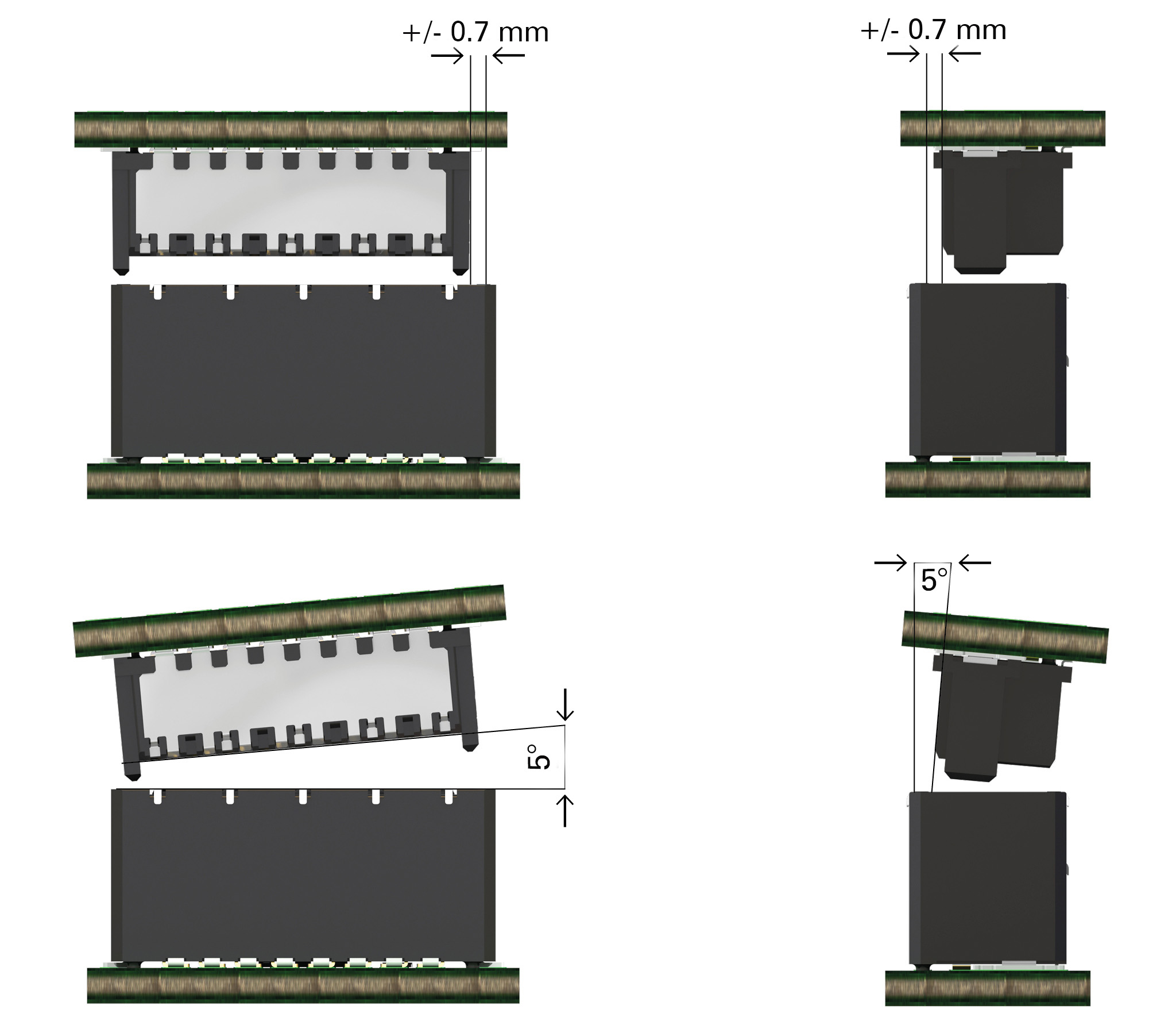
Compensation for misalignment up to 0.7 mm during installation
Tapered edges on the sides of the insulating bodies allow the plug and socket to compensate for misalignment of up to 0.7 mm during the mating process. During mating, the blade and spring contacts are guided into position relative to one another in such a way that a secure connection is established and “over-insertion” is prevented.
High tolerance compensation during operation
When mated, the socket and plug can tolerate a relative displacement of up to 0.4 mm. This provides considerable flexibility in terms of tolerance considerations for your applications. It also allows you to place multiple connector pairs on a printed circuit board without compromising contact reliability.
When all the top features are complemented by exceptional ruggedness, that’s Zero8 from ept. Whether it’s the clever anti-twist protection during connection or the misalignment compensation of up to 0.7 mm during installation, Zero8 delivers on its promises.
Free white paper on ruggedness »
Request a free sample box »
Find more information here.
Free white paper on ruggedness »
Request a free sample box »
Find more information here.

For further information,
please contact us.
Submit an inquiry via the form
: +49 8861 2501 0
sales@ept.de
please contact us.
Submit an inquiry via the form
: +49 8861 2501 0
sales@ept.de