DIN 41612 PCB connector

DIN Anwendung C ML C FL inkl Name

Features

  • Various termination technologies available
  • ; first mate, last break contacts upon request
  • ; pre-alignment
  • ; various tail lengths
  • ; up to 160 contacts per connector; connectors with
  • two to five rows available
  • ; connectors with a 2.54 mm pitch or 5.08 mm pitch; extensive
  • accessories such as shrouds, board lock, keying
  • Switch connectors for daisy chaining
  • are internationally approved, e.g., according to UL
    • Signal transmission up to 1.5 A
  • ; current transmission up to 5.6 A or 15 A
    • Mounting clips and keying provide developers and users with added security and a wide range of application possibilities.

Applications

  • backplane daughtercard, 19-inch rack technology (VME)
  • , board-to-board, parallel or stacked
  • , high current,
  • used as a peripheral connector for external interfaces from the wiring side
  • over longer distances via ribbon cable
Filter
Straight Female
Straight Male
90° Female
90° Male
switching connector
VME 64x

DIN 41612 VME 64x header Part No. 306-61067-12

DIN VME64x FL Foto
Connector length: 4.6 mm, Number of poles: 160, Press-fit technology, Grade 1, without a flange
Perpendicular
Press-fit
Rugged
DIN 41612 VME 64x header Part No. 306-61067-12 - Technical data

Basics

SpecificationIEC 61076-4-113
Performance Level1
No. of Contacts160
Termination TechnologyPress-fit technology
Termination Length4.6 mm
Operating Temperature Range-55°C to +125°C

Material

Insulator MaterialGlass-fiber-reinforced PBT, UL 94 V-0
CTI value
IEC 60112
200
Contact Materialcopper alloy

Mechanical

Pitch2.54 mm
Mating Force160 N
Separating Force per Pin> 0.15 N
Durability500 insertion cycles

Electrical

Operational Current1.5 A
Test Voltage1000 V
Contact Resistance20 mΩ
Clearance and Creepageabc ≥ 1.2 mm, zd ≥ 1.0 mm
Insulation Resistance104 MΩ

Approval / Compliance

UL fileE130314
EnvironmentRoHS compliant
Stock Check
You will be redirected to an external page with the Supplyframe offer. By loading the content you accept the data processing by Supplyframe.
You can view Supplyframe's privacy policy here.

Yes, load content from Supplyframe

DIN 41612 VME 64x header Part No. 306-62067-12

DIN VME64x FL Foto
Connector length: 4.6 mm, Number of poles: 160, Press-fit technology, Grade 1, ANSI flange
Perpendicular
Press-fit
Rugged
DIN 41612 VME 64x header Part No. 306-62067-12 - Technical data

Basics

SpecificationIEC 61076-4-113
Performance Level1
No. of Contacts160
Termination TechnologyPress-fit technology
Termination Length4.6 mm
Operating Temperature Range-55°C to +125°C

Material

Insulator MaterialGlass-fiber-reinforced PBT, UL 94 V-0
CTI value
IEC 60112
200
Contact Materialcopper alloy

Mechanical

Pitch2.54 mm
Mating Force160 N
Separating Force per Pin> 0.15 N
Durability500 insertion cycles

Electrical

Operational Current1.5 A
Test Voltage1000 V
Contact Resistance20 mΩ
Clearance and Creepageabc ≥ 1.2 mm, zd ≥ 1.0 mm
Insulation Resistance104 MΩ

Approval / Compliance

UL fileE130314
EnvironmentRoHS compliant
Stock Check
You will be redirected to an external page with the Supplyframe offer. By loading the content you accept the data processing by Supplyframe.
You can view Supplyframe's privacy policy here.

Yes, load content from Supplyframe

DIN 41612 VME 64x header Part No. 306-67069-14

DIN VME64x FL Foto
Connection length: 17 mm, with a planting zone of 1, Number of poles: 160, Press-fit technology, Grade 1, ANSI flange
Perpendicular
Press-fit
Rugged
DIN 41612 VME 64x header Part No. 306-67069-14 - Technical data

Basics

SpecificationIEC 61076-4-113
Performance Level1
No. of Contacts160
Termination TechnologyPress-fit technology
Termination Length17 mm
Operating Temperature Range-55°C to +125°C

Material

Insulator MaterialGlass-fiber-reinforced PBT, UL 94 V-0
CTI value
IEC 60112
200
Contact Materialcopper alloy

Mechanical

Pitch2.54 mm
Mating Force160 N
Separating Force per Pin> 0.15 N
Durability500 insertion cycles

Electrical

Operational Current1.5 A
Test Voltage1000 V
Contact Resistance20 mΩ
Clearance and Creepageabc ≥ 1.2 mm, zd ≥ 1.0 mm
Insulation Resistance104 MΩ

Approval / Compliance

UL fileE130314
EnvironmentRoHS compliant
Stock Check
You will be redirected to an external page with the Supplyframe offer. By loading the content you accept the data processing by Supplyframe.
You can view Supplyframe's privacy policy here.

Yes, load content from Supplyframe

DIN 41612 VME 64x header Part No. 306-60067-12

DIN VME64x FL Foto
Connector length: 4.6 mm, Number of poles: 160, Press-fit technology, Grade 1, DIN flange
Perpendicular
Press-fit
Rugged
DIN 41612 VME 64x header Part No. 306-60067-12 - Technical data

Basics

SpecificationIEC 61076-4-113
Performance Level1
No. of Contacts160
Termination TechnologyPress-fit technology
Termination Length4.6 mm
Operating Temperature Range-55°C to +125°C

Material

Insulator MaterialGlass-fiber-reinforced PBT, UL 94 V-0
CTI value
IEC 60112
200
Contact Materialcopper alloy

Mechanical

Pitch2.54 mm
Mating Force160 N
Separating Force per Pin> 0.15 N
Durability500 insertion cycles

Electrical

Operational Current1.5 A
Test Voltage1000 V
Contact Resistance20 mΩ
Clearance and Creepageabc ≥ 1.2 mm, zd ≥ 1.0 mm
Insulation Resistance104 MΩ

Approval / Compliance

UL fileE130314
EnvironmentRoHS compliant
Stock Check
You will be redirected to an external page with the Supplyframe offer. By loading the content you accept the data processing by Supplyframe.
You can view Supplyframe's privacy policy here.

Yes, load content from Supplyframe

DIN 41612 VME 64x header Part No. 306-65069-14

DIN VME64x FL Foto
Connection length: 17 mm, with a planting zone of 1, Number of poles: 160, Press-fit technology, Grade 1, DIN flange
Perpendicular
Press-fit
Rugged
DIN 41612 VME 64x header Part No. 306-65069-14 - Technical data

Basics

SpecificationIEC 61076-4-113
Performance Level1
No. of Contacts160
Termination TechnologyPress-fit technology
Termination Length17 mm
Operating Temperature Range-55°C to +125°C

Material

Insulator MaterialGlass-fiber-reinforced PBT, UL 94 V-0
CTI value
IEC 60112
200
Contact Materialcopper alloy

Mechanical

Pitch2.54 mm
Mating Force160 N
Separating Force per Pin> 0.15 N
Durability500 insertion cycles

Electrical

Operational Current1.5 A
Test Voltage1000 V
Contact Resistance20 mΩ
Clearance and Creepageabc ≥ 1.2 mm, zd ≥ 1.0 mm
Insulation Resistance104 MΩ

Approval / Compliance

UL fileE130314
EnvironmentRoHS compliant
Stock Check
You will be redirected to an external page with the Supplyframe offer. By loading the content you accept the data processing by Supplyframe.
You can view Supplyframe's privacy policy here.

Yes, load content from Supplyframe

DIN 41612 VME 64x header Part No. 306-66069-14

DIN VME64x FL Foto
Connection length: 17 mm, with a planting zone of 1, Number of poles: 160, Press-fit technology, Grade 1, without a flange
Perpendicular
Press-fit
Rugged
DIN 41612 VME 64x header Part No. 306-66069-14 - Technical data

Basics

SpecificationIEC 61076-4-113
Performance Level1
No. of Contacts160
Termination TechnologyPress-fit technology
Termination Length17 mm
Operating Temperature Range-55°C to +125°C

Material

Insulator MaterialGlass-fiber-reinforced PBT, UL 94 V-0
CTI value
IEC 60112
200
Contact Materialcopper alloy

Mechanical

Pitch2.54 mm
Mating Force160 N
Separating Force per Pin> 0.15 N
Durability500 insertion cycles

Electrical

Operational Current1.5 A
Test Voltage1000 V
Contact Resistance20 mΩ
Clearance and Creepageabc ≥ 1.2 mm, zd ≥ 1.0 mm
Insulation Resistance104 MΩ

Approval / Compliance

UL fileE130314
EnvironmentRoHS compliant
Stock Check
You will be redirected to an external page with the Supplyframe offer. By loading the content you accept the data processing by Supplyframe.
You can view Supplyframe's privacy policy here.

Yes, load content from Supplyframe
Accessories

DIN 41612 Coding, Types B and C Part No. 104-19003

for types B and C, prevents incorrect insertion of assemblies, 1 piece equals 4 wedges
DIN 41612 Coding, Types B and C Part No. 104-19003 - Technical data

Basics

SpecificationIEC 60603-2 (DIN 41612)
Operating Temperature Range-55°C to +125°C

Material

Insulator MaterialPBT

Approval / Compliance

EnvironmentRoHS compliant
Stock Check
You will be redirected to an external page with the Supplyframe offer. By loading the content you accept the data processing by Supplyframe.
You can view Supplyframe's privacy policy here.

Yes, load content from Supplyframe

DIN 41612 Shroud C/R Part No. 115-15302

DIN C R Uebergabestecker Foto
for PCB thickness 3.2 mm, for post length 17 mm, C/R
Perpendicular
DIN 41612 Shroud C/R Part No. 115-15302 - Technical data

Basics

SpecificationIEC 60603-2 (DIN 41612)
Operating Temperature Range-55°C to +125°C

Material

Insulator MaterialGlass-fiber-reinforced PBT, UL 94 V-0

Mechanical

Pitch2.54 mm

Approval / Compliance

EnvironmentRoHS compliant
Stock Check
You will be redirected to an external page with the Supplyframe offer. By loading the content you accept the data processing by Supplyframe.
You can view Supplyframe's privacy policy here.

Yes, load content from Supplyframe

DIN 41612 Shroud C/R Part No. 115-15401

DIN C R Uebergabestecker Foto
for PCB thickness 2.4 mm, for post length 13 mm, C/R
Perpendicular
DIN 41612 Shroud C/R Part No. 115-15401 - Technical data

Basics

SpecificationIEC 60603-2 (DIN 41612)
Operating Temperature Range-55°C to +125°C

Material

Insulator MaterialGlass-fiber-reinforced PBT, UL 94 V-0

Mechanical

Pitch2.54 mm

Approval / Compliance

EnvironmentRoHS compliant
Stock Check
You will be redirected to an external page with the Supplyframe offer. By loading the content you accept the data processing by Supplyframe.
You can view Supplyframe's privacy policy here.

Yes, load content from Supplyframe

DIN 41612 Shroud C/R Part No. 115-15301

DIN C R Uebergabestecker Foto
for PCB thickness 2.4 mm, for post length 17 mm, C/R
Perpendicular
DIN 41612 Shroud C/R Part No. 115-15301 - Technical data

Basics

SpecificationIEC 60603-2 (DIN 41612)
Operating Temperature Range-55°C to +125°C

Material

Insulator MaterialGlass-fiber-reinforced PBT, UL 94 V-0

Mechanical

Pitch2.54 mm

Approval / Compliance

EnvironmentRoHS compliant
Stock Check
You will be redirected to an external page with the Supplyframe offer. By loading the content you accept the data processing by Supplyframe.
You can view Supplyframe's privacy policy here.

Yes, load content from Supplyframe

DIN 41612 Shroud C/R Part No. 115-15402

DIN C R Uebergabestecker Foto
for PCB thickness 3.2 mm, for post length 13 mm, C/R
Perpendicular
DIN 41612 Shroud C/R Part No. 115-15402 - Technical data

Basics

SpecificationIEC 60603-2 (DIN 41612)
Operating Temperature Range-55°C to +125°C

Material

Insulator MaterialGlass-fiber-reinforced PBT, UL 94 V-0

Mechanical

Pitch2.54 mm

Approval / Compliance

EnvironmentRoHS compliant
Stock Check
You will be redirected to an external page with the Supplyframe offer. By loading the content you accept the data processing by Supplyframe.
You can view Supplyframe's privacy policy here.

Yes, load content from Supplyframe

DIN 41612 shroud is stiff Part No. 115-15405

DIN C R Uebergabestecker Foto
for PCB thickness 3.2 mm, for post length 13 mm, C/R is stiff
Perpendicular
DIN 41612 shroud is stiff Part No. 115-15405 - Technical data

Basics

SpecificationIEC 60603-2 (DIN 41612)
Operating Temperature Range-55°C to +125°C

Material

Insulator MaterialGlass-fiber-reinforced PBT, UL 94 V-0

Mechanical

Pitch2.54 mm

Approval / Compliance

EnvironmentRoHS compliant
Stock Check
You will be redirected to an external page with the Supplyframe offer. By loading the content you accept the data processing by Supplyframe.
You can view Supplyframe's privacy policy here.

Yes, load content from Supplyframe

DIN 41612 Shroud, stiff-running, without flange Part No. 115-15408

DIN C R Uebergabestecker Foto
for PCB thickness 3.2 mm, for post length 13 mm, C/R stiff, without flange
Perpendicular
DIN 41612 Shroud, stiff-running, without flange Part No. 115-15408 - Technical data

Basics

SpecificationIEC 60603-2 (DIN 41612)
Operating Temperature Range-55°C to +125°C

Material

Insulator MaterialGlass-fiber-reinforced PBT, UL 94 V-0

Mechanical

Pitch2.54 mm

Approval / Compliance

EnvironmentRoHS compliant
Stock Check
You will be redirected to an external page with the Supplyframe offer. By loading the content you accept the data processing by Supplyframe.
You can view Supplyframe's privacy policy here.

Yes, load content from Supplyframe

DIN 41612 Shroud C/R with Nut Part No. 115-15701

DIN C R Uebergabestecker Foto
for PCB thickness 3.2 mm, for post length 13 mm, C/R with nut
Perpendicular
DIN 41612 Shroud C/R with Nut Part No. 115-15701 - Technical data

Basics

SpecificationIEC 60603-2 (DIN 41612)
Operating Temperature Range-55°C to +125°C

Material

Insulator MaterialGlass-fiber-reinforced PBT, UL 94 V-0

Mechanical

Pitch2.54 mm

Approval / Compliance

EnvironmentRoHS compliant
Stock Check
You will be redirected to an external page with the Supplyframe offer. By loading the content you accept the data processing by Supplyframe.
You can view Supplyframe's privacy policy here.

Yes, load content from Supplyframe

DIN 41612 Shroud C/R with Nut Part No. 115-15702

DIN C R Uebergabestecker Foto
for PCB thickness 3.2 mm, for post length 17 mm, C/R with nut
Perpendicular
DIN 41612 Shroud C/R with Nut Part No. 115-15702 - Technical data

Basics

SpecificationIEC 60603-2 (DIN 41612)
Operating Temperature Range-55°C to +125°C

Material

Insulator MaterialGlass-fiber-reinforced PBT, UL 94 V-0

Mechanical

Pitch2.54 mm

Approval / Compliance

EnvironmentRoHS compliant
Stock Check
You will be redirected to an external page with the Supplyframe offer. By loading the content you accept the data processing by Supplyframe.
You can view Supplyframe's privacy policy here.

Yes, load content from Supplyframe

DIN 41612 Shroud VME Part No. 315-15401

DIN Shroud VME Foto
for PCB thickness 3.4 mm, Post length: 17 mm, x = 6 mm
Perpendicular
DIN 41612 Shroud VME Part No. 315-15401 - Technical data

Basics

SpecificationIEC 61076-4-113
Operating Temperature Range-55°C to +125°C

Material

Insulator MaterialGlass-fiber-reinforced PBT, UL 94 V-0

Mechanical

Pitch2.54 mm

Approval / Compliance

EnvironmentRoHS compliant
Stock Check
You will be redirected to an external page with the Supplyframe offer. By loading the content you accept the data processing by Supplyframe.
You can view Supplyframe's privacy policy here.

Yes, load content from Supplyframe

DIN 41612 Shroud VME Part No. 315-15402

DIN Shroud VME Foto
for PCB thickness 4.6 mm, Post length: 17 mm, x = 4.8 mm
Perpendicular
DIN 41612 Shroud VME Part No. 315-15402 - Technical data

Basics

SpecificationIEC 61076-4-113
Operating Temperature Range-55°C to +125°C

Material

Insulator MaterialGlass-fiber-reinforced PBT, UL 94 V-0

Mechanical

Pitch2.54 mm

Approval / Compliance

EnvironmentRoHS compliant
Stock Check
You will be redirected to an external page with the Supplyframe offer. By loading the content you accept the data processing by Supplyframe.
You can view Supplyframe's privacy policy here.

Yes, load content from Supplyframe

DIN 41612 Coding for Types H11 and H15 Part No. 114-30000

Plastic tab for coding
DIN 41612 Coding for Types H11 and H15 Part No. 114-30000 - Technical data

Basics

SpecificationIEC 60603-2 (DIN 41612)
Stock Check
You will be redirected to an external page with the Supplyframe offer. By loading the content you accept the data processing by Supplyframe.
You can view Supplyframe's privacy policy here.

Yes, load content from Supplyframe
Other number of contacts? Other stacking heights? alternative plating? Individual assembly? Lagging contacts?
» Not the right one for you? Request a customized connector now!
Thank you very much! We will review your request and get back to you.

If you have any questions, please feel free to contact us by email or phone at any time.

No matching product found - Request this product now:

Fields marked with * are required.
You can view our privacy policy here.

DIN 41612 Printed Circuit Board Connectors (PCB connector) — the EPT Quality Promise

PPE Automotive
Personal and Individual
Short communication channels, fast response times, and the same experienced contacts year after year guarantee you high-quality information as well as time and cost savings.
Of course, we at ept are always happy to welcome you to one of our plants!
Lagerlogistik
Reliable and Fast
ept combines long-standing reliability and stability with a high degree of flexibility thanks to its extensive independence from suppliers and its in-house toolmaking division (toolmaking). For you, this means a shorter “time to market,” quick and clear answers to your questions, as well as the ability to independently manage and prioritize your projects.
PPE IC
Outstanding Overall Quality
The lowest field failure rate available on the market and high “on-time delivery” guarantee you a low risk of failure and help prevent costly line stoppages. This claim is supported by a robust quality and environmental management system, certified to ISO 9001, ISO 14001, and TS 16949.
In-house manufacturing using our own tooling, along with our internal electroelectroplating, ensures high product quality and continuous, reliable testing.

Our PCB connectors: ✓ reliable, ✓ durable, ✓ available in many variants

DIN 41612 printed circuit board connectors (PCB connector) are high-quality industrial connectors that have been tried and tested thousands of times and have been in use for over 50 years.
icon robust 3
Rugged
: The DIN41612 PCB connector can withstand even harsh environmental conditions, such as shock, vibration, corrosive gases, and much more. With our specialized contact technologies, they ensure robust construction and high tolerances during contact formation and mating. For assembly, you can choose between press-fit technology, solder termination, hand soldering, WireWrap, Faston, cut-to-fit terminals for ribbon cable, or THRT. 
icon zuverlaessig
Reliable
: Our PCB connectors featuring Tcom press® press-fit technology have the lowest field failure rate available on the market. Combined with high on-time delivery, we guarantee you a low risk of failure and the avoidance of costly line stoppages. We will coordinate delivery dates for shipments directly from us with you. Should delivery delays occur due to external circumstances, we will notify you as soon as possible and arrange an alternative delivery date. For orders placed with our partners, please contact the partner directly.
icon varianten 2
Wide Variety of Variants With 12 basic shapes and 25 variants,
we offer nearly the full range of DIN 41612 industrial connectors. Whether spring-loaded connectors (Female), blade connectors (Male), switch connectors (switching connector), VME64x, or insulation-displacement connectors (Schneidklemm-Variante), our DIN 41612 PCB connectors and board connectors are highly versatile and reliable. If you require other DIN 41612 PCB connectors, we can provide additional variants quickly upon request.
icon verfuegbar
Availability
: We are largely independent of suppliers. Our in-house toolmaking division (toolmaking) enables us to offer long-term reliability and stability combined with a high degree of flexibility. As a result, you benefit from a faster “time to market.” Our service team answers your questions quickly and reliably.
icon made in eu
Made in the EU
: In-house manufacturing using our own tooling, along with our internal electroelectroplating, ensures high product quality and continuous, reliable testing. Our DIN 41612 industrial connectors are manufactured in Germany and the Czech Republic.
icon zertifiziert 1
Certified
EPT is certified to ISO 9001, ISO 14001, and TS 16949. You can find our certifications, approvals, and test reports for the U.S. and Canada, as well as our RoHS, REACH, POP, recycling, and “conflict minerals” questionnaires here.

Features of the DIN 41612 connector for board-to-board applications

The DIN 41612 connector remains widely used, particularly as an industrial connector. For example, the VME bus—which has been available on the market for over 35 years—is based on DIN connectors. This has enabled it to secure a very strong position in the industrial PC sector, and it continues to be used in new developments. The wide variety of different types and termination technologies (press-fit technology, dip soldering, hand soldering, wire-wrap technology, crimp, and THR) available for DIN connectors cover a broad spectrum of applications. Furthermore, their robust and reliable construction ensures that these PCB connectors will continue to be relevant in the future. Today, DIN 41612 connectors are used in applications ranging from signal transmission to the transmission of higher currents. And this applies to all areas of industrial electronics: from control technology and motor controls to industrial PCs.

Further information on DIN 41612 Leiterplatten-connector:

DIN Federleiste
Female Type C Connector

Details at a Glance

image
pitch: 2.54 mm
image
Internal female contact
image
keying
image
PBT
image
press-fit zone Tcom press
image
Flange for Board-Lock
DIN Messerleiste
Male Type C Connector

Details at a Glance

image
pitch: 2.54 mm
DIN Loet Feature Zeichnung 180x180
solder termination
image
Flange for Board-Lock
image
PBT
image
keying

press-fit technology: Tcom press by ept

Einpresstechnik
In light of the increasing miniaturization of assemblies and higher component density on printed circuit boards, the solderless “press-fit technology” method is being used more and more frequently. Press-fit connections are created by pressing a connector pin into a through-hole in the printed circuit board. plated through hole (PTH) enables an electrical connection between opposing layers of the printed circuit board. To achieve this, a hole is drilled through the board, and copper is applied as the carrier material.

The connection is made using a defined and controlled force—an enormous advantage for consistent quality and fast, trouble-free processing. What makes this special is that the press-fit pin has a larger diagonal dimension than the hole diameter of the printed circuit board. The flexibility lies in the press-fit zone.
Press-in tools allow multiple connector to be pressed in at the same time. Unlike with soldering, the printed circuit boards are not subjected to thermal stress during this process. A gas-tight, durable, and mechanically and electrically conductive connection with low contact resistance is formed between the press-fit pin and the hole wall.

Your benefits of the DIN 41612 connector thanks to Tcom press® press-fit technology

  • Electrical, mechanical, gas-tight, corrosion-resistant, and low-resistance connection
  • High holding forces
  • No soldering defects, flux residues, or similar issues
  • No additional cleaning required
  • No thermal stress on the Euro board
  • No thermal stress on electronic components
  • Recycling possible by simply
  • pressing out components More efficient and cost-effective assembly process
  • Double-sided assembly of the PCB possible

last-mate contact on the DIN 41612 connector

The DIN 41612/IEC 60603-2 connector family (connector family) consists of 12 basic types with supplementary variants. For DIN-connector of types B, C, R, D, and E, male contacts with a 0.8 mm or 1.0 mm lead-in can be used in any position of rows a, b, c, d, and e. For type F and G, lead-in distances of 1.3 mm are possible.

Why use a leading contact or last-mate contact?
Leading and last-mate contacts are used in electrical engineering to prevent voltage spikes and thus overvoltage. With these contacts, the connection is established first or last, respectively, and is also broken first or last, respectively.

Do you need a connector with leading or last-mate contacts?
No problem. We offer custom loadings for DIN types B, C, R, D, E, F, and G. The leading contact can be installed in any desired position.

Contact us »

DIN 14162 PCB Connectors - Types

signal connector in the pitch 2.54 mm
DIN 41612 type B, Q + DIN 41612 type C, R

The two-row type B and the three-row DIN 41612 Type C consist of an angled blade connector and a straight spring/socket strip. If straight blade connectors and angled spring connectors are required, the two-row type Q and the three-row type R are available.

All four series are available in half-width and one-third-width versions. Connection options include press-fit, wave soldering, and THR.

Since the B and Q types, as well as the C and R types, can be combined, it is possible to connect printed circuit boards at a 90° angle, in parallel, or even horizontally. 

DIN 41612 Connectors - types B + Q:
- type B: angled Male, straight Female
- type Q: straight Male, angled Female
- 64
contacts - Length: 95 mm, Width: 8.6 mm

DIN 41612 Connectors - type B/2 + Q/2:
- type B: angled Male, straight Female
- type Q: straight Male, angled Female
- 32
contacts- Length: 55 mm, width: 8.6 mm

DIN 41612 connectors - type B/3 + Q/3
:- type B: angled Male, straight Female
- type Q: angled Male, straight Female
- 20
contacts- Length: 39 mm, width: 8.6 mm

DIN 41612 connector—type C + R:
—type C: angled Male, straight Female
—type R: straight Male, angled Female
—96 contacts
—length: 95 mm, width: 11 mm

DIN 41612 connector—type C/2 + R/2:type
R: straight Male, angled Female
- type R: straight Male, angled Female
- 48 contacts-
Length: 55 mm, Width: 11 mm

DIN 41612 connector - type C/3 + R/3:
- type C: angled Male, straight Female
- type R: angled Male, straight Female
- 30 contacts-
Length: 39 mm, width: 11 mm All

of the aforementioned types of type can transmit operating currents of up to 1.6 A at 20 °C.

DIN signal connector are frequently used in the IT/computing sector to connect plug-in card to backplane.

Signal and power (30A) in a DIN 41612 type PCB connector

The Type M connector offers both high current- and signal contacts in a single connector. The straight Female and the angled Male can be configured with either 6 signal and 10 coaxial contacts, or 24/8, 42/6, 60/4, and 78/2. Furthermore, the M-series are also available in M/2 – 30/2 and M/3 – 12/2.

This PCB connector variant is used, for example, in control systems for filling lines.

pitch 5.08 mm – Power (5.6 A)
DIN 41612 type D, E + DIN 41612 type F, G + DIN 41612 type F flat, G flat

Those who need to transmit currents of up to 5.6 A can use the two-row DIN 41612 type D and three-row DIN 41612 type E connectors. Both variants have a pitch of 5.08 mm. By default, the Male is angle, and the Female is straight.

Designed for the same application but with a more robust construction are the DIN 41612 Type F (three-row) and DIN 41612 Type G (four-row) PCB connectors. For both PCB connector-Typen, the socket strip is available not only in the standard height but also in a lower-profile version. This allows for different board-to-board distances.
The DIN 41612 type F and DIN 41612 type G are primarily used in railway.

type D (Type D)
:- 32
contacts- 2 rows

type E (Type E)
:- 48
contacts- 2 rows

type F (Type F)
:- 48 contacts-
3 rows

type F, flat
:- 48
contacts- 3 rows

type G (Type G)
:- 64
contacts- 4 rows

type G, flat
:- 64
contacts- 4 rows

pitch 5.08 mm with Faston connector 15A
DIN 41612 H11, DIN 41612 H15, mixed type DIN 41612 H7/F24

For a Faston connection, you’ll need DIN 41612 H11, DIN 41612 H15, or the mixed type DIN 41612 H7/F24. The spring-loaded connector (Female) for the H11 and H15 is available in two different heights. The H7/F25 is an interesting connector strip, featuring 7 Faston connectors (15 A) and 24 power contacts (5.6 A).

VME 64x backplane Connectors
for Vita Multi-User Bus Systems

A special feature of the DIN 41612 series is the 5-row VME64x Female. With 160 contacts, this Female is available in 3 different variations and 2 contact lengths, using press-fit technology. The current VME64 version features a bus width of 64 bits.

The DIN 41612 VME64x Female is used, among other applications, in the aviation, aerospace, and defense industries.

DIN 41612 Switch Connector
for Daisy Chaining

Many bus systems in automation technology are wired according to the daisy-chain principle. Looping signal lines through multiple circuit boards in series is a common practice. However, if individual circuit boards are removed, jumpers must be inserted. This problem can be solved more elegantly using switch connectors. When the daughter daughtercard is removed, the contact is automatically short-circuited, eliminating the need to manually insert jumpers.

Overview of Models

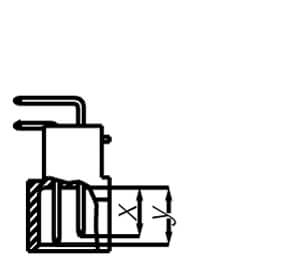
din bauform B
DIN 41612 type B, B/2,
B/3• Standard (X): 4.9•
first mate (Y) + 1.0 mm: 5.9•
last mate (Y) -0.8 mm: 4.1
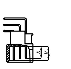
din bauform C
DIN 41612 type C, C/2,
C/3• Standard (X): 4.9•
first mate (Y) + 1.0 mm: 5.9•
last mate (Y) -0.8 mm: 4.1
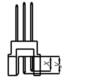
din bauform R
DIN 41612 type R, R/2, R/3
mating side
• Standard (X): 4.9•
first mate (Y) +0.8 mm: 5.7 | + 1.0 mm: 5.9•
last mate (Y) -0.4 mm: 4.5 | -0.8 mm: 4.1
termination side
• Standard (X): 13.0•
first mate (Y) + 0.8 mm: 13.8•
last mate (Y) -0.4 mm: 12.6 | -0.8: 12.2
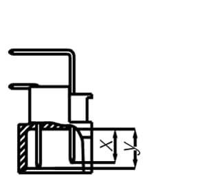
din bauform D
DIN 41612 type
D• Standard (X): 4.9•
first mate (Y) + 0.8 mm: 5.7
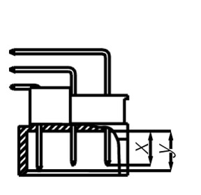
din bauform E
DIN 41612 type E (pitch 2.54 mm)
• Standard (X): 4.9•
first mate (Y) + 0.8 mm: 5.7 (Series a, c, e)

DIN 41612 type E (pitch 5.08 mm)
• Standard (X): 4.9•
first mate (Y) + 0.8 mm: 5.7 (Series a)
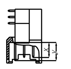
din bauform F
DIN 41612 type
F• Standard (X): 6.1•
first mate (Y) + 1.3 mm: 7.4
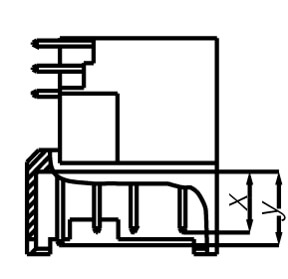
din bauform G
DIN 41612 type
G• Standard (X): 6.1•
first mate (Y) + 1.3 mm: 7.4

ept connector DIN 41612 / IEC 60603-2 product series

Produktmanager Schmid DIN Homepage
“connector that comply with today’s IEC 60603-2 (formerly DIN 41612) have been in use for over 50 years. And for good reason. Even though technology has evolved and, in the age of IoT and Industry 2.0, applications are becoming smaller yet still contain more assemblies, DIN connectors are still just as relevant as they were five decades ago—thanks to their compatibility with the latest board designs, facilitated by their wide variety of types, numbers of positions, and termination technologies.

In addition to soldering and wire wrap techniques, ept also offers the option to obtain the connector connector family in the Tcom press press-fit zone developed by ept.
The ept DIN 41612 / IEC 60603-2 product series comprises 12 basic body styles as well as additional complementary versions with 2.54 mm or 5.08 mm pitch. The selection includes both signal connectors with a current-current-carrying capacity of up to 1.5 A and power connectors with up to 5.6 A or even 15 A per pin. This wide range of variants enables the use of the connector connector family in an extremely broad range of applications. Standardization ensures compatibility among connectors from different manufacturers."

Wolfgang Schmid, Product Manager, ept GmbH
DIN 41612 / IEC 60603-2 PCB connector

FAQ: Questions and Answers About the DIN 41612 PCB Connector

How can DIN 41612 connector be processed?What currents can be transmitted using DIN 41612 connectors?Are the DIN 41612 connector RoHS-compliant?What misalignment do DIN 41216 connector tolerate during mating?Are there suitable tools available for processing ept’s DIN 41216 connectors? Which
How can DIN 41612 connector be processed?

Depending on the connection technology (termination technology), this includes press-fit or soldering technology (solder termination), as well as through-hole reflow technology, FASTON termination, or insulation displacement connection (IDC)

What currents can be transmitted using DIN 41612 connectors?

The selection includes both signal connectors with a current-current-carrying capacity of up to 1.5 A and power connectors with up to 5.6 A or even 15 A per pin.

Are the DIN 41612 connector RoHS-compliant?

Yes, all of them.

What misalignment do DIN 41216 connector tolerate during mating?

The DIN connectors feature a high misalignment tolerance. For example, when mating blade connectors and spring-contact connectors (Female), a 1 mm radial misalignment (center misalignment) is permitted in both the longitudinal and transverse axes. The angular misalignment tolerance is 4° longitudinally and 2° transversely.

Are there suitable tools available for processing ept’s DIN 41216 connectors? Which

Yes, we offer you the right tools, tailored to your connector.

Customer reviews of DIN-style PCB connectors

We respect our clients’ desire for discretion and therefore do not cite any sources below.
However, we unconditionally guarantee the authenticity of these statements.

Our customers must be able to reliably adapt to our devices even under harsh conditions. That is why we have relied for years on the high quality standards of ept’s DIN connector.

Qualitätsleiter Leistungselektronik

“The wide selection of press-fit connectors, including the angled versions, really won me over.”

Fertigungsplaner Board-Fertigung

By using the THR variant, the wave soldering step can be eliminated, making the process significantly more cost-effective.

Fertigungsplaner Board-Fertigung

Your message has been sent.

Thank you for your interest—we will process your request as soon as possible.

Contact Form

Fields marked with * are required.

Personal information

Your message

Privacy Policy

You can view our privacy policy here.

Your message has been sent.

Thank you for your interest—we will process your request as soon as possible.

Contact Form

Fields marked with * are required.

Personal information

Recall

Your message

I am interested in

Information materials

Privacy Policy

You can view our privacy policy here.

Thank you very much for your interest

You can download the white paper here:

Download the white paper

Before you can download the white paper, please fill out the following fields. Thank you.

Fields marked with * are required.

Personal information

Privacy Policy

You can view our privacy policy here.

Your message has been sent.

Thank you very much for your interest in our networking event following Electronica. We will review your request and confirm your participation as soon as possible.

Inquiry Form

Fields marked with * are required.

Personal information

Privacy Policy

You can view our privacy policy here.

Thank you very much!

We will contact you shortly to discuss your requirements. We will prepare and send you a detailed report on the high-speed characteristics as well as S-parameter for simulating your own design.

Request HighSpeed specifications and S-parameter to simulate your own design

Fields marked with * are required.
You can view our privacy policy here.

Thank you for your inquiry

We will review your request and get back to you as soon as possible.

Your requirements for the connector

Fields marked with an * are required; please fill them in.

Contact person

Your request

Wrong file format! Please select a PDF or JPG file.
You can view our privacy policy here.

Thank you for your inquiry

We will review your request and get back to you as soon as possible.

Request a quote for connector customization

Fields marked with an * are required; please fill them in.

Contact person

Your request

Wrong file format! Please select a PDF or JPG file.
You can view our privacy policy here.