


High speed without risks
Big Data and related technologies are demanding ever-higher data transfer rates. At the same time, electronic components must not only become faster and smarter, but also smaller. This creates specific risks in data transmission and, consequently, new challenges for connector technology. What should you look for in your connectors to prevent signal interference?

The ongoing digitalization across all industries—such as the Industrial Internet of Things, Industry 4.0, smart grids, and smart homes—requires high-speed data transmission from the sensor to the cloud. However, this applies not only to sensors but also to industrial control systems, camera systems, data communications, and server applications: signals must be reliably transmitted at 20 Gbps and higher. In addition to high speed, IIoT, Big Data, and related technologies bring another trend: electronic components must not only become faster and smarter, but also smaller. This ongoing miniaturization makes it more difficult for developers to pass the mandatory EMC tests required by the European directive. This is because electronic components within an assembly can act as both a sink and a source of interference, and the close placement of sensitive components increases the risk of mutual interference.
Definition of the vehicle electrical system: Decentralized, domain- and zone-based architecture

The traditional distributed architecture in automobiles consists of up to 100 control units, with each unit assigned a specific function: engine control, airbags, ABS/ESP, seat adjustment, climate control, … Each control unit operates independently and communicates with other control units via gateways.
Over the past decades, the decentralized architecture has undergone significant growth, with each new functionality requiring an additional control unit. Today, however, it is reaching its limits: increasing functionalities significantly raise the installation and wiring costs within the vehicle.
In domain architecture, the control units are grouped into different functional areas. Each domain is responsible for a specific area of the vehicle, such as powertrain, infotainment, or safety. The overarching control of a domain is performed by a standalone high-performance computer (HPC). This coordinates the control units within its domain. For the safety functional area, these would include, for example, control units for driver assistance systems, ABS/ESP, and steering systems.
Compared to decentralized architecture, the reduced number of installed control units decreases wiring and installation costs. This domain architecture can thus also effectively contribute to cost and weight reduction compared to the decentralized architecture. Additionally, new functions can be integrated later with minimal effort.
In zone architecture, the structure is not based on domains but on local zones. For example, multiple functionalities are bundled within a single zone in the vehicle. Accordingly, functions such as the powertrain and infotainment can also be combined and processed in a single zone controller. The various zone controllers are managed by a central HPC. The advantage is clear: a reduction in the number of control units and their wiring by up to 50 percent.
Requirements for the HPC and its connectors

The demands this places on an HPC are significant: not least, the processing of imaging data in the infotainment sector or in camera systems for autonomous driving requires secure, high-speed data transmission with low latency. At the same time, signal transmission must not fail under any circumstances—its reliability must be guaranteed at all times.
High performance, fast, and above all, reliable data transmission—sometimes under adverse environmental conditions—are therefore also requirements placed on the connectors used.
The “readability” of a signal can be illustrated using what is known as an eye diagram. This indicates whether a transmitted signal can be unambiguously assigned to the digital states 1 or 0 in the receiver.
To do this, a signal passes through a defined transmission path, where it is recorded, superimposed, and displayed by an oscilloscope. In this way, all possible signal waveforms can be superimposed on top of one another. In theory, the transitions between logical states are infinitely steep, and the signal lines run exactly on top of one another. Due to external interference and internal degradation of the signal pairs, the signal rise flattens out, and the amplitude changes. This results in the characteristic eye-shaped pattern.

In the center of the diagram, the eye mask is visible. Signal identification is not feasible within this region.
The two eye diagrams illustrate the effects of cable length and impedance using the example of the ept Colibri connectors in the 16+ Gbit/s and 10 Gbit/s versions. The example demonstrates how a significant improvement in signal integrity was achieved through the further development of the contact design (see Fig. XX). Thanks to a shorter cable length and 100Ω impedance, the eye of the 16+ Gbit/s version of the Colibri® forms more clearly than in the previous 10 Gbit/s version of the Colibri®—the signal pairs can be unambiguously interpreted.
The two eye diagrams illustrate the effects of cable length and impedance using the example of the ept Colibri connectors in the 16+ Gbit/s and 10 Gbit/s versions. The example demonstrates how a significant improvement in signal integrity was achieved through the further development of the contact design (see Fig. XX). Thanks to a shorter cable length and 100Ω impedance, the eye of the 16+ Gbit/s version of the Colibri® forms more clearly than in the previous 10 Gbit/s version of the Colibri®—the signal pairs can be unambiguously interpreted.
Since high-speed signals are particularly susceptible to electromagnetic interference, they require special signal protection. A connector can act as both a source of interference and a sink. For this reason, signal protection using a shielding plate is recommended to protect the sensitive signals from external interference.
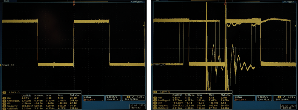
Figure 4 demonstrates that even a small electrical impulse can distort the useful signal. The receiver can no longer clearly interpret the digital states of the HDMI signal after just a short burst impulse of 0.5 kV, whereas the signal transmission of the shielded connector remains stable even at 4.4 kV.
Figure 4 demonstrates that even a small electrical impulse can distort the useful signal. The receiver can no longer clearly interpret the digital states of the HDMI signal after just a short burst impulse of 0.5 kV, whereas the signal transmission of the shielded connector remains stable even at 4.4 kV.

Using the coupling inductance LK as an EMC parameter, the connector can be described by analyzing the electrical conditions in both modes—source and sink. The unit Henry is used for this purpose. This applies to both immunity and emissions. If the induced voltage (Uind), the generator voltage (UGen), and the generator constant (kGen) are known, the specific maximum permissible coupling inductance (L) for a given application can be determined using the following formula:
LK = Uind / (UGen * kGen).
The coupling inductance also helps the user define the appropriate connector in terms of its electromagnetic compatibility and avoid costly and time-consuming trial-and-error testing in the EMC laboratory. For example, for an HDMI signal, a case-specific maximum coupling inductance of 47 picohenry (pH) was determined at a voltage of 4.4 kV; if this value is exceeded, the signal can no longer be transmitted without interference.
But it is not only electromagnetic interference that jeopardizes the transmission of high-speed signals. Especially in automotive applications, connectors are repeatedly exposed to extreme environmental conditions such as vibration and shock. To ensure uninterrupted signal transmission even in harsh environments, the connector must be particularly robust. In this context, contact design, contact system, and connection technology play a decisive role.
Contact system as an influencing factor

Traditional two-part connectors feature a blade contact and a spring contact. However, in the event of a strong shock, the blade strip can detach from the spring strip. To prevent such a contact interruption, a double-sided spring strip can be used to ensure redundancy and thus contact reliability, as the second spring ensures that signal transmission is maintained at all times via at least one contact point (Fig. 5).

In contrast, connectors with a so-called “gender-neutral” contact system are even more robust. The key feature here is that the contact geometries of the mating pairs—plug and socket—are identical. Both therefore feature both a spring and a blade. As a result, each pin is contacted by two springs, and the plug and socket are interlocked so that they cannot separate from one another. While a double-sided spring strip always ensures at least one contact point under mechanical stress, the interlocked geometries in gender-neutral contact systems ensure that signal transmission always occurs via two contact points. This high level of redundancy thus enables maximum contact reliability (Fig. 5).

Surface-mount technology (SMT) is recommended as the connection method for creating a durable bond between the printed circuit board and the connector. Using solder paste, the connectors are soldered to specific connection areas on the printed circuit board, known as solder pads. The solder is then melted and subsequently solidified in a so-called reflow oven. SMT enables the creation of stable connections between the connector and the PCB. However, several criteria must be met: First, for a solder joint compliant with the IPC-A-610 standard, the correct ratio of solder ball, solder pad, and solder paste must be maintained. Only in this way can a high-quality connection be established that meets IPC Class 3 requirements, making it suitable for use in high-performance electronics. Failures in signal transmission must be ruled out at all times in this class. An optimal solder joint is characterized by uniform meniscus formation. The contact must be completely surrounded by the solder meniscus to achieve the best holding forces on the printed circuit board (Fig. 9).
The coplanarity of the contact pads is essential for an excellent connection, and this is verified through a 100% automated inspection during the manufacturing process.
Conclusion
Current developments in the automotive industry are constantly placing new demands on the connectors used in vehicles. At first glance, it might seem that the role of these connectors is becoming less significant due to the reduced number of control units. Upon closer inspection, however, it becomes clear that their role is actually gaining importance precisely because of this shift toward centralized data processing using HPC: Reliability in signal transmission has never been more critical than it is today.