






The right process, the right connector
How to Ensure Component Protection—The Right Process, the Right connector
The electronics industry is undergoing a transformation: whether in the automotive sector, solar and wind power, or industrial automation, electrification is taking place across all sectors. However, with the steady increase in connectivity, the number of electronic failures has also risen in recent years—by as much as 29%, according to the Center for Automotive Research. Depending on the expected environmental influences, component protection for electronic components is therefore necessary. This ensures that the electronics are reliably protected—but to achieve this, users also need a corresponding potting-compatible connection solution.
Growing Demand for Component Protection Methods
Various methods protect electronic components from shock, vibration, moisture, dirt, high temperatures, prolonged temperature fluctuations, and the resulting damage. Component protection can therefore contribute significantly to improving the service life, functional safety, and reliability of end products.
For this reason, component protection methods are already regularly used in many applications: e-mobility, industrial automation, rail applications, medical technology (medical technology), wind power (wind power), and solar technology, communications electronics, agriculture, and household appliances—medical technology is used almost everywhere today. A growing challenge in this context is the increasing trend toward miniaturization. Electronics are becoming smaller and smaller and require different protective measures to increase creepage distances and eliminate clearance distances.
Depending on the stress and operating conditions of the components, one therefore chooses between various methods: Potting-potting, conformal coating, and hot-melt molding are the most popular among them.
Do you have any specific questions?

Component protection methods: Potting potting

One- and two-component potting compounds are used very frequently. With two-component potting compounds, resin and hardener are mixed in a specific ratio using appropriate machinery and, as standard, poured into the cavity via a static mixing tube. Thus, this cold potting is a non-molding process and requires a housing into which the potting compound is poured.
Potting potting offers many advantages: Not only does it provide excellent electrical insulation, high heat dissipation, and vibration and shock reduction, but it also offers resistance to chemicals, moisture, thermal shock, and cycling; protects electronics from dust and moisture; and possesses flame-retardant properties.
Depending on specific requirements, epoxy, polyurethane, and silicone resins are typically used. They all differ in terms of their properties (Table 1).
In addition to the materials mentioned, there are also special encapsulants and casting resins. However, these are used only under extreme conditions. For example, in accordance with ATEX requirements, they protect against explosions by preventing the chemical reaction between an ignition source, a flammable substance, and oxygen. Furthermore, they provide electrical insulation against high voltage (up to 30 kV/mm), protect against overheating caused by localized heat generation, and, with an IP68 protection rating, offer protection against dust and prolonged submersion. Potting potting
offers users a wide range of possibilities. Typical products in which this process is used include battery packs, power and control electronics, chargers, explosion-protected electronics, sensors, monitors, and displays.
offers users a wide range of possibilities. Typical products in which this process is used include battery packs, power and control electronics, chargers, explosion-protected electronics, sensors, monitors, and displays.
Component protection method: conformal coating

conformal coating is used to coat printed circuit boards either completely or selectively. In the case of selective plating, only the necessary areas of the printed circuit board are covered with a protective layer. Generally, a distinction is made between two types of coating: Thin-film coating, with its fast curing time and optimized viscosity, ensures high cost-effectiveness in manufacturing processes. In contrast, thick-film coating provides particularly high edge and surface protection, safeguarding electronic assemblies especially against extreme humidity. In both cases, the conformal coatings build up layer thicknesses of only 30–2,000 µm after drying. This means the electronic assembly can still be installed even in tight spaces.
Due to the varying viscosities of the conformal coatings—and thus their differing flow characteristics—the DAM & FILL principle is frequently applied to assembled electronic assemblies. Here, a thixotropic conformal coating is used to create a “dam” around components that must not be encapsulated, such as connector. The remaining components are then coated with a low-viscosity conformal coating (“fill”). Various polymer materials are used
for conformal coating. For example, users can choose between silicone-based and UV-curing products, among others. The former are ideally suited for harsh operating conditions—such as in the aerospace or offshore industries—due to their wide temperature range of -40°C to +200°C. The latter consist of acrylates and polyurethanes or hybrids of both materials. They are characterized above all by the fact that they cure very quickly through UV initiation and offer excellent thermal shock resistance.
The applications for conformal coatings are diverse and range from the automotive sector to railway, sensor technology, industrial electronics, medical technology, as well as the aforementioned Offshore-wind power and aerospace technology.
Component protection method: hot-melt molding

hot-melt molding is a special form of potting. In this process, the assembly is encased in a material in a single step, creating a housing structure while simultaneously protecting the assembly. The electronics are not damaged in the process, as the low-viscosity, thermoplastic materials have a low processing temperature and are processed at a much lower injection pressure than in standard plastic injection molding. On the one hand, this protects the components; on the other, it allows the thermoplastics to cure quickly and makes the process relatively cost-effective.
Low-pressure injection molding (low-pressure molding) thus enables even sensitive components such as contacts, sensors, printed circuit boards, and coils to be encased, bonded, or sealed to IP68 standards in an environmentally friendly manner, thereby protecting them even from the most severe conditions.
One industry heavily affected by external influences is agriculture, for example. Machinery in this sector is exposed to varying weather conditions on a daily basis. hot-melt molding is perfectly suited for protecting its electronics: It provides reliable, long-lasting protection against moisture, temperature fluctuations, corrosion, and vibrations.
Conclusion

Potting, conformal coating, or hot-melt molding: Which component protection method is most suitable always depends on the specific application of the electronics and the associated requirements. There is no one-size-fits-all solution.
Challenges with connector

Extreme temperatures, dirt, and moisture, as well as chemical or mechanical stress: With the appropriate component protection method, the electronics are shielded from nearly any external influence. However, one aspect must be considered: Potting (potting) is only possible if the functionality of the installed components is not compromised by the materials used. This also requires a connection solution that is compatible with the potting compound—therefore, the use of standard PCB connectors is not an option. The reason for this is the typically two-part spring-blade contact technology, in which the potting potting compound can penetrate the vulnerable mating area and thus interfere with the contact.
With conventional connectors, the contact area must therefore be sealed using the “dam and fill” method prior to potting to avoid any risk of interference from the potting compound (Fig. 2). The concern here is that, in the contact area, the potting compound could, on the one hand, impair the contact points and thus interrupt signal transmission. On the other hand, it would inhibit the relaxation properties of the spring.
To still allow for “potting” while ensuring the required reliability, it is recommended to choose a one-piece connection solution—that is, a connector that does not require the conventional “mating area.” With such a one-piece connector, it is impossible for the “potting compound” to penetrate the contact area.
press-fit technology as the termination technology of choice
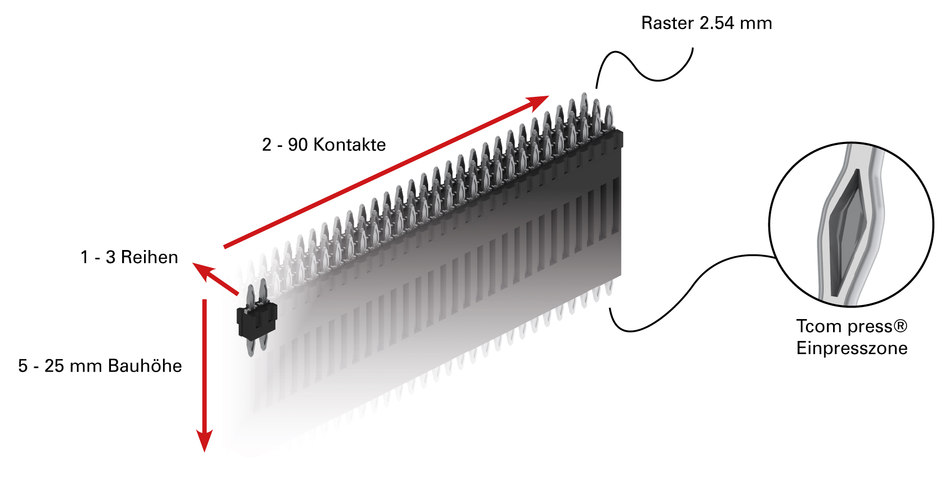
Accordingly, one-piece connectors provide the necessary IP degree of protection for these materials to enable potting—and thus a durable and robust connection solution. However, the choice of termination technology also plays an important role here. With the help of press-fit zones on both sides, the connection area (termination area) becomes gas-tight due to the cold welding (cold welding) between the copper sleeve and the press-fit zone (press-fit zone), thus forming a pottable connection between two printed circuit boards—a solution that has already proven itself billions of times in the field.
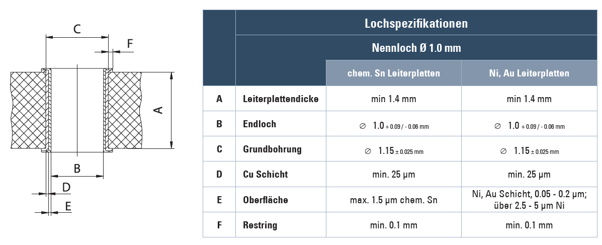
However, to ensure this gas-tight connection, it is absolutely necessary to implement the plated through hole (PTH) in accordance with the ept specification:
By eliminating the mating area, the connector, in combination with the press-fit technology, can withstand shock loads of up to 200 g. Neither material movement caused by large temperature fluctuations nor the influence of corrosive gases affects the connection. The press-fit technology increases reliability many times over compared to solder termination, as neither cold joints nor broken solder joints can occur. Furthermore, this approach eliminates the need for complex selective soldering, expensive cable solutions, and standoff, allowing developers not only to save space on the printed circuit board but also to reduce costs by up to 50 percent.
A single component establishes both a mechanical and an electrical connection. Especially for modular assemblies with configurable functions or varying performance levels, the press-fit process can be seamlessly integrated at the end of the assembly process. Here, different modules can be mounted on base printed circuit boards as desired. This allows for the production of a wide variety of products in a single, rapid step. Since the assembly can also be encapsulated at the end, the electrical and mechanical connections remain reliably intact. potting
allows users to provide maximum protection for their electronic assemblies against aggressive environmental influences. However, anyone considering component protection for their application must also take into account the selection of a suitable connector in combination with the appropriate termination technology. One-piece, press-fit, and potted—with this combination, electronic assemblies are equipped to withstand (almost) all external influences.
Learn more about “press-fit technology” in the free white paper

Would you like to gain even more in-depth technical knowledge about press-fit technology?
For comprehensive details on the fundamentals of press-fit technology, we’d be happy to send you our free white paper:
Request white paper »
For comprehensive details on the fundamentals of press-fit technology, we’d be happy to send you our free white paper:
Request white paper »
Suitable press-fit connector

flexilink b-t-b
Our flexilink b-t-b connector meets exactly these requirements for robustness and reliability and is also available in the proven press-fit technology.
For more information about the product, click here:
Flexilink »
Our flexilink b-t-b connector meets exactly these requirements for robustness and reliability and is also available in the proven press-fit technology.
For more information about the product, click here:
Flexilink »

Any questions?
Then please contact us!
Submit an inquiry via the form
+49 (0) 8861 2501 0
sales@ept.de
Then please contact us!
Submit an inquiry via the form
+49 (0) 8861 2501 0
sales@ept.de